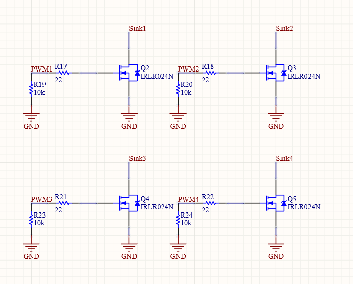
PWM
Design uses IRLR024N NMOS as main PWM fet. It’s sure is overkill for this project but since it’s sponsor by Telok and it’s free so why not. It’s main features:
Vds Max = 55V
Id Max = 17A
VGS(th) = min 1V Max 2V
VGS Max= +/- 16V
FET’s have basic 22 ohm serial resistor at gate and 10k ohm pulldown at side of processor.
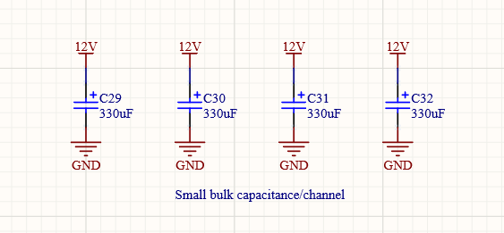
Some bulk capacitance are also added/channel for just in case if needed. They have not been assembled at PCB.
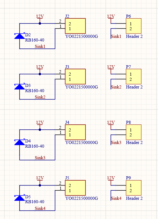
There is also protection diode/channel to protect FET’s from inductive load spikes. Purpose of pinheaders is just to make easier to connect PC-fans to PCB.